
This project aims to build a digital clock using a real-time clock chip (DS3231) with battery backup, a liquid crystal display (JHD 204A), and an Arduino Uno board.
Let us try to design our own real-time digital clock that can be used in time-related projects, like keeping the data of a sensor with time, a time-based alarm system, or a power cut-off system.
You will also learn how to program the DS3231 clock chip and the LCD in an Arduino environment.
A real-time digital clock (RTC) is often required in projects and designs where we need to deal with time. RTC helps in keeping track of time even when the main processor is asleep or switched off.
It is because of RTC that your PC/laptop clock keeps showing the correct time even after it has been switched off for some time, or even when the computer’s battery is removed for replacement with a new one. RTC module has its own small coin cell that runs for years and helps keep track of time when the whole circuit is powered off.
The components required for the circuit are listed in the Bill of Material table.
| Bill of Material | |
| Components | Quantity |
| RTC DS3231 (MOD1) | 1 |
| CR2032 coin cell | 1 |
| LCD JHD 204A / 1602 I2C / SPI (MOD2) | 1 |
| 10k pot (P1) | 1 |
| 220Ω resistor (R1) | 1 |
| Arduino Uno with USB cable | 1 |
| Power adaptor (12V, 2A) | 1 |
| Jumper wires (male-female) | 20 |
The project has two parts. In the first part, we learn how to interface the LCD to Arduino Uno. In the second part, we add a clock chip to this setup and display the time.
This RTC clock is to be made using Arduino Uno and programmed in Arduino IDE. So, download Arduino IDE and unzip it in a convenient folder. Fig. 1 shows the Arduino Uno board.
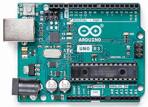
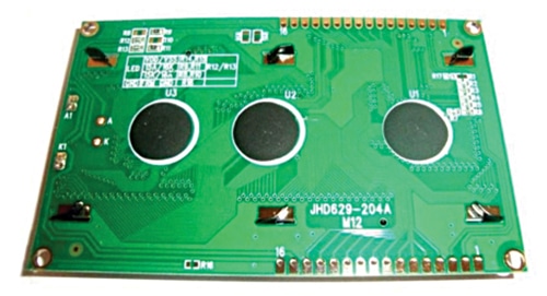
Fig. 2(a) shows the display side (front side) of the LCD, while Fig. 2(b) shows its backside. The time is displayed on liquid crystal display JHD204A. This is a 20-column, 4-row display with a blue backlight but you can also use a 16×2 LCD with two rows of the display. Each character is displayed in a dot-matrix manner.
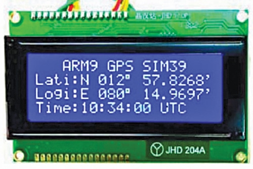
The LCD has 16 pins but only 12 pins are used here. Out of these, 4 are for data lines, 3 for control lines, and the rest are for power and ground lines. (We are not using DB0, DB1, DB2, and DB3 here.)
Pin No. 3 is for controlling the contrast. A 10k trim pot is connected to this pin. Adjust this pot to get optimum performance. Pin No. 15 of the LCD is connected to 5V through a 220-ohm resistor.
If you are using the SPI to I2C converter with display, you got the four pins SCL, SDA, GND, and VCC. Here in this design, SPI is used.
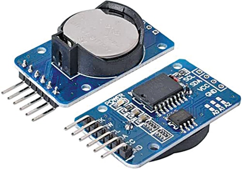
RTC DS3231 is a real-time clock module with battery backup. The battery to be used is a CR2032 button cell, which can maintain the time for at least one year. The RTC uses a two-wire I2C interface. This means that for communicating with Uno, the RTC requires only two pins, SDA and SCL. Fig. 3 shows the RTC DS3231.
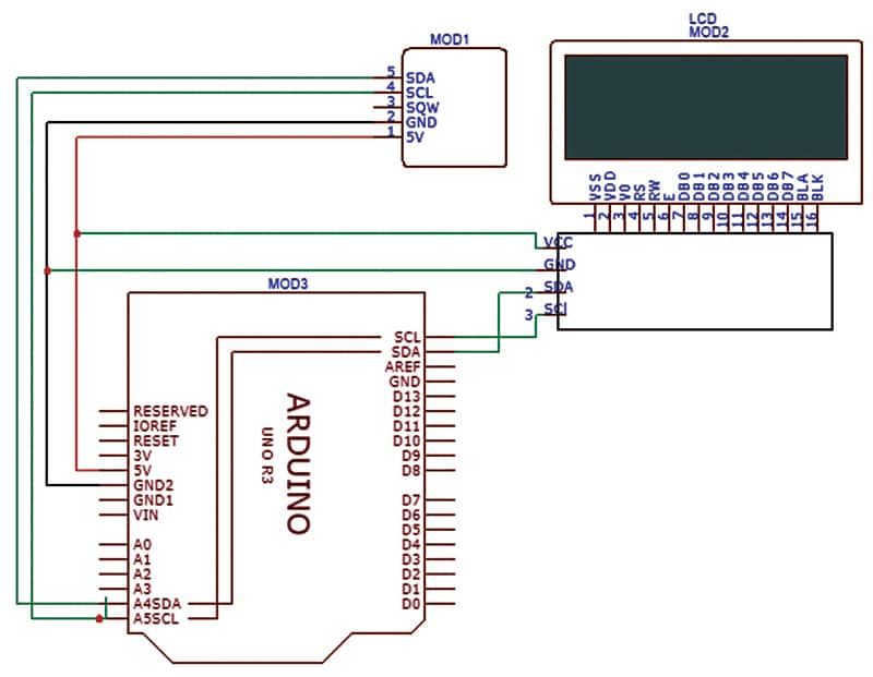
As mentioned earlier, the circuit is divided into two parts. In the first part, we see how to interface the LCD to Arduino Uno (see Fig. 4). In the second part, we add a clock chip to this setup and display the time (see Fig. 5).
Real-Time Digital Clock Circuit Diagram
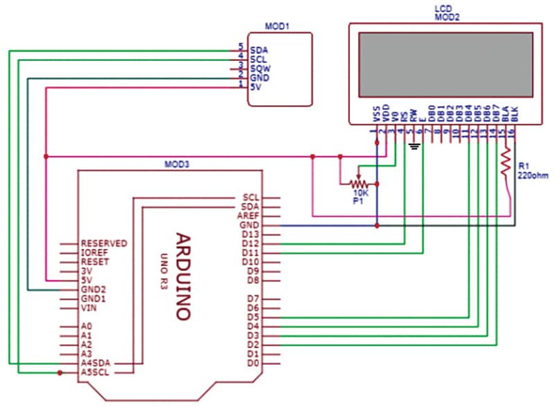
The LCD and RTC are connected to the Arduino as shown in Fig. 4. DS3231 RTC has six pins out of which only four are used here. The I2C interface of the RTC has two pins, SDA and SCL, which are connected directly to the SDA and SCL pins on the Arduino. The VCC and GND pins of the RTC are connected to the 5V and GND of the Arduino Uno board.
Real-Time Digital Clock – Arduino Code
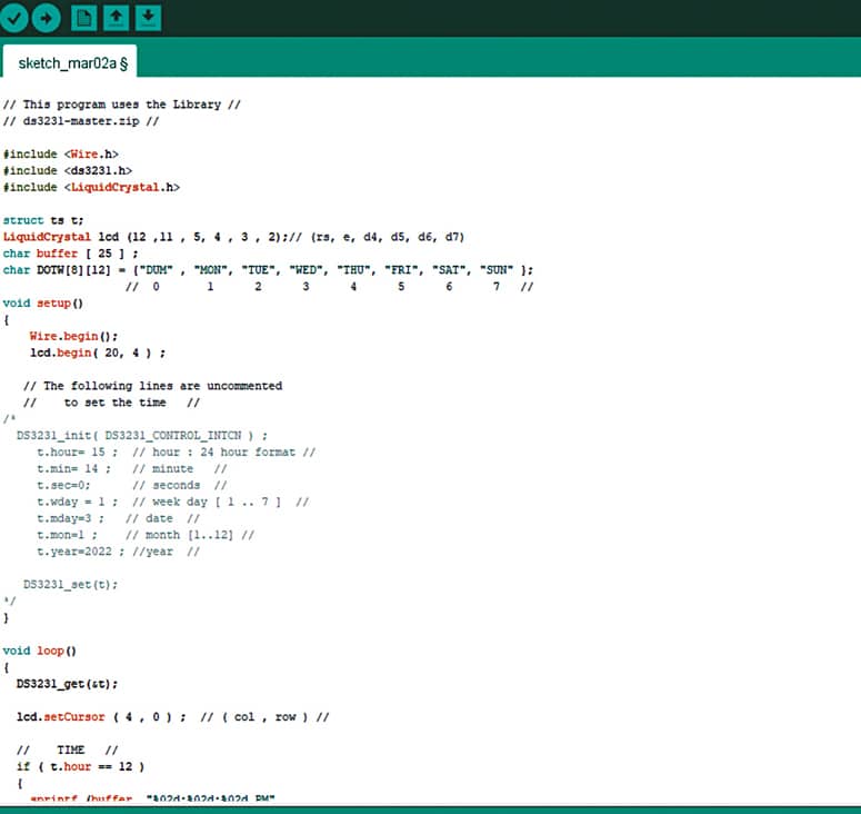
A snippet of the source code is shown in Fig. 6. The code has three header files. You have to download the ds3231-master.zip library from the internet and add it to the Arduino library.
For this open Arduino IDE, go to Sketch→Include Library→Add Zip Library and select the zip file.
In line No.10, we create an lcd object, as before. In line No.12, we create an array of strings. All arrays have the starting index 0, but we are not using this index. We ignore index 0 and start counting the days from 1 to 7 (1 is for Monday and 7 is for Sunday).
Lines 22 to 31 are commented out. This routine is used for setting the time. We fill the parameters properly, uncomment them, and then load the code into the Arduino.
After that, we comment them and once again load the code into the Arduino. Now even if you switch off the power, the RTC will maintain the time (because of the battery).
The RTC gives the time in a 24-hour format. So, some computations are needed to convert it to a 12-hour format. Lines 42 to 54 do just that. They decide whether it is AM or PM and calculate the hour. Then they print (display) the time and the date.
After uploading the source code to the Arduino board, fix the circuit in a wooden or plastic box with the LCD in the front and easy access to the reset button of Uno.
When you apply power to the circuit, it will automatically display the correct time. If the displayed time is incorrect, press the reset button and the correct time should get displayed now. This completes the Arduino-based real-time digital clock project.
For more such interesting projects, you can check Electronics Projects Ideas
Download Source Code
Hemakumar K., with 27 years of teaching and other experience, retired from the Government College of Engineering Kannur, Kerala, as Associate Professor