
During ironing the clothes there is a possibility for the cloth to get burnt due to the ironbox kept over the cloth unattended when attending any phone calls or engaging in any other activities. To overcome this issue we have proposed a solution to automatically control the ironbox wirelessly, when unattended through deatacheable motion sensor. The uniqueness of the system is it has a wireless control unit and a deatacheable sensing unit which could be suitable for different types of ironbox. During ironing, the accelerometer and gyroscope sensor is used to detect the motion and position (vertical or horizontal) of the iron box, respectively and send the data to the wireless control unit. The iron box is switched on only when it is in motion and placed in vertical position,or otherwise it will switched off through the wireless control unit.

System design
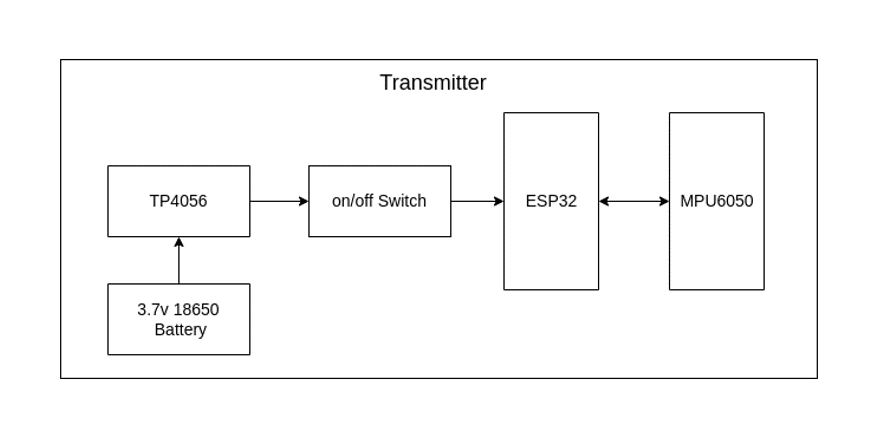
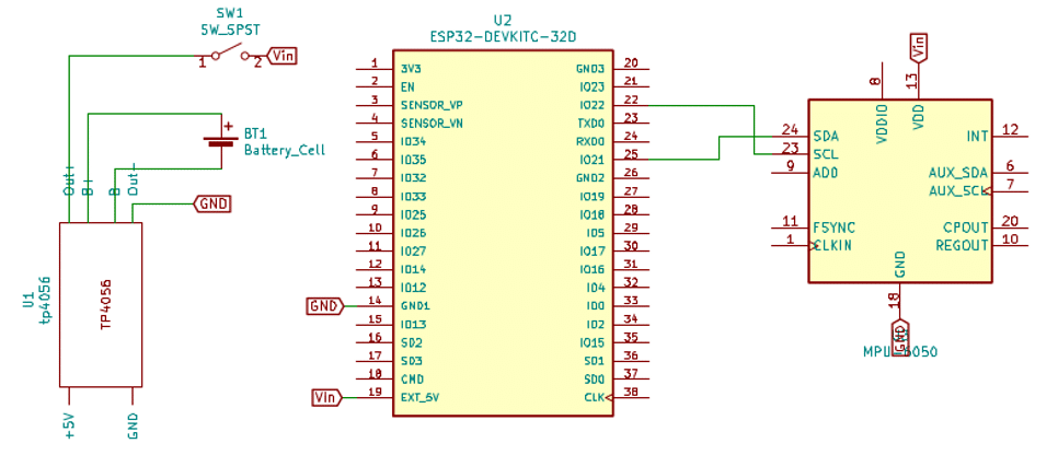
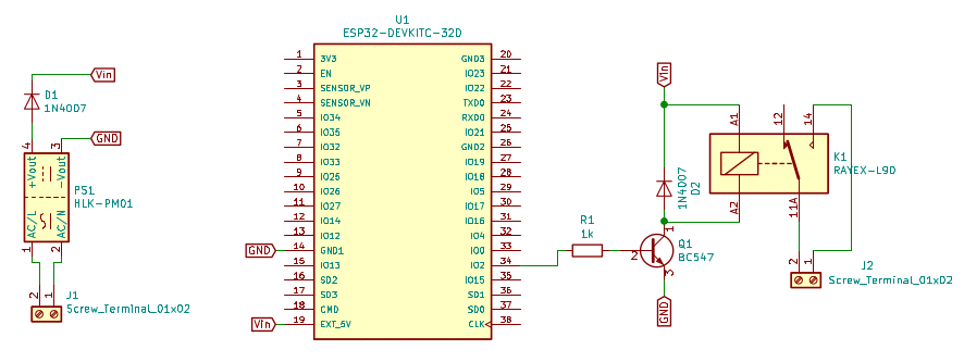
This project is divided into two section one is Sensing part another one is Triggering part.The sensing part is called as Transmitter and Triggering part is called as Receiver. Fig.2. and Fig.3. shows Block diagram of the Transmitter part and Receiver part. The Transmitter system uses MPU6050 as sensor to get the ironbox movement and it can detect x-axis, y-axis, z-axis. This sensor is I2C compatable and the data is acquired and processed using the ESP32 microcontroller. The ESP32 further process the data and send it to the Receiver part using ESP-NOW protocol. The Receiver part will receive the command if the command is valid (eg. 0 or 1), based on the command receiver part will trigger the relay.ESP32 microcontroller transceiver is used for getting valid commands and to do actuation through relay drive circuitry. The Transmitter system uses 3.7 V Lithium ion rechargeable battery and it is charged through TP4056 charging module. The charging module is connected with a 5 V USB charger. And Receiver system uses 230v AC to 5v DC converter, 5v relay module is used to drive the ironbox. Whenever a valid command is received ESP32 triggers a HIGH or LOW signal to the GPIO pins connected with relay with respect to the command and relay actuates ironbox connected.

| Reference | Quantity | Value/Model | Part description |
| U1 | 1 | TP4056 | TP4056 on a breakout board |
| BT1 | 1 | Battery Cell | 18650 3.7 V Lithium-ion rechargeable battery |
| SW1 | 1 | SW_SPST | Switch for input power |
| U2 | 1 | ESP32 DEVKITC-32D | ESP32 development board |
| U3 | 1 | MPU6050 | MPU6050 3 axis gyroscope and accelerometer |
Table.1. Part List for Transmitter
| Reference | Quantity | Value/Model | Part description |
| J1,J2 | 2 | Screw_terminal_01x02 | Screw terminal block for Input and Output |
| PS1 | 1 | HLK-PM01 | 5v Ac to Dc Power supply |
| D1, D2 | 2 | 1N4007 | General purpose diode |
| R1 | 1 | 1KOhm | ¼ Watt through hole resistor |
| Q1 | 1 | BC547 | NPN Transistor |
| U1 | 1 | ESP32 DEVKITC-32D | ESP32 development board |
| K1 | 1 | RAYEX-L90 | 30-amps T-type Relay |
Table.2. Part List for Receiver
MPU6050
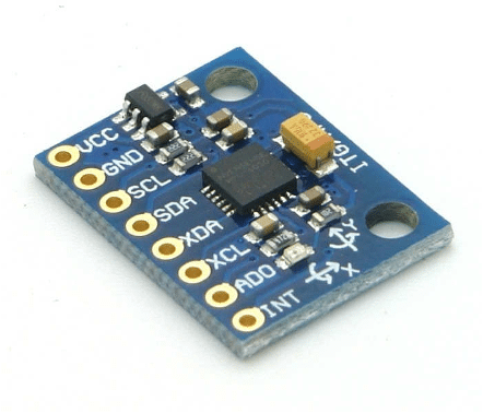
MPU6050 sensor module is complete 6-axis Motion Tracking Device. It combines 3-axis Gyroscope, 3-axis Accelerometer and Digital Motion Processor all in small package. Also, it has additional feature of on-chip Temperature sensor. It has I2C bus interface to communicate with the microcontrollers.
3-Axis Gyroscope
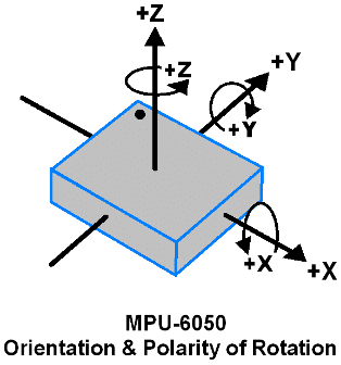
The MPU6050 consist of 3-axis Gyroscope with Micro Electro Mechanical System(MEMS) technology. It is used to detect rotational velocity along the X, Y, Z axes as shown in below figure. When the gyros are rotated about any of the sense axes, the Coriolis Effect causes a vibration that is detected by a MEM inside MPU6050. The resulting signal is amplified, demodulated, and filtered to produce a voltage that is proportional to the angular rate. This voltage is digitized using 16-bit ADC to sample each axis. The full-scale range of output are +/- 250, +/- 500, +/- 1000, +/- 2000. It measures the angular velocity along each axis in degree per second unit.
3-Axis Accelerometer
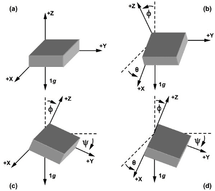
The MPU6050 consist 3-axis Accelerometer with Micro Electro Mechanical (MEMs) technology. It used to detect angle of tilt or inclination along the X, Y and Z axes as shown in below figure. Acceleration along the axes deflects the movable mass. This displacement of moving plate (mass) unbalances the differential capacitor which results in sensor output. Output amplitude is proportional to acceleration. 16-bit ADC is used to get digitized output. The full-scale range of acceleration are +/- 2g, +/- 4g, +/- 8g, +/- 16g. It measured in g (gravity force) unit. When device placed on flat surface it will measure 0g on X and Y axis and +1g on Z axis.
ESP NOW
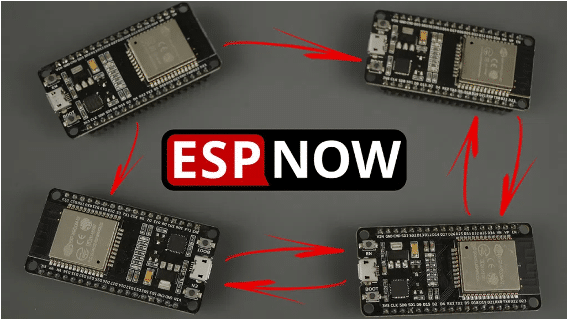
ESP-NOW is a protocol developed by Espressif, which enables multiple devices to communicate with one another without using Wi-Fi. The protocol is similar to the low-power 2.4GHz wireless connectivity. The pairing between devices is needed prior to their communication. After the pairing is done, the connection is safe and peer-to-peer, with no handshake being required. This means that after pairing a device with each other, the connection is persistent. In other words, if suddenly one of your boards loses power or resets, when it restarts, it will automatically connect to its peer to continue the communication. In simple words, ESP-NOW is a fast communication protocol that can be used to exchange small messages (up to 250 bytes) between ESP32 boards. ESP-NOW is very versatile and you can have one-way or two-way communication in different setups.
ESP-NOW One-Way Communication

One way communication means One ESP32 board sending data to another ESP32 board.This configuration is very easy to implement and it is great to send data from one board to the other like sensor readings or ON and OFF commands to control GPIOs. One ESP32 board sending the same or different commands to different ESP32 boards. This configuration is ideal to build something like a remote control. To communicate via ESP-NOW, you need to know the MAC Address of the ESP32 receiver. Each ESP32 has a unique MAC Address and that’s how we identify each board to send data to it using ESP-NOW.
TP4056 Charger Module
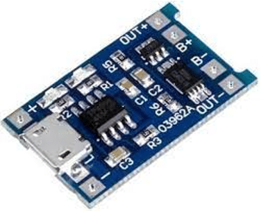
The TP4056 lithium battery charger module comes with circuit protection and prevents battery over-voltage and reverse polarity connection. The TP4056 module lights up a red LED when it’s charging the battery and lights up a blue LED when the battery is fully charged. connect the battery positive terminal to the B+ pad, and the battery negative terminal to the B- pad. The OUT+ and OUT- are the battery outputs. These lithium batteries output up to 4.2V when fully charged (although they have 3.7V marked in the label).
SPDT T- Type Relay
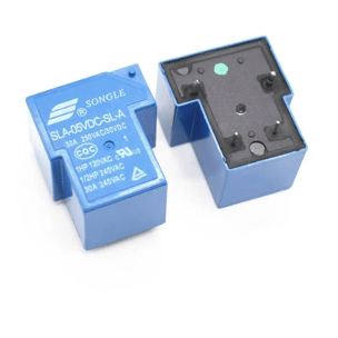
Single-pole, double-throw (SPDT) T-Type relay shown in Fig, can be controlled directly via a microcontroller using relay driver circuit and switch up to 30A at 250V AC. The inputs of the relay are isolated from 230V mains to protect the delicate control circuitry. The relay output pins are connected to 3-pin 250V, 10A electrical socket.
Source code
For Receiver:
#include
#include
int count = 0;
// Structure example to receive data
// Must match the sender structure
typedef struct struct_message
char a[32];
int b;
float c;
bool d;
struct_message;
// Create a struct_message called myData
struct_message myData;
// callback function that will be executed when data is received
void OnDataRecv(const uint8_t * mac, const uint8_t *incomingData, int len)
memcpy(&myData, incomingData, sizeof(myData));
Serial.print(“Bytes received: “);
Serial.println(len);
Serial.print(“Char: “);
Serial.println(myData.a);
Serial.print(“Int: “);
Serial.println(myData.b);
Serial.println();
if(myData.b == 1)
digitalWrite(2,HIGH);
count =0;
if(myData.b == 0)
digitalWrite(2,LOW);
count =0;
void setup()
// Initialize Serial Monitor
Serial.begin(115200);
pinMode(2,OUTPUT);
// Set device as a Wi-Fi Station
WiFi.mode(WIFI_STA);
// Init ESP-NOW
if (esp_now_init() != ESP_OK)
Serial.println(“Error initializing ESP-NOW”);
return;
// Once ESPNow is successfully Init, we will register for recv CB to
// get recv packer info
esp_now_register_recv_cb(OnDataRecv);
void loop()
count++;
delay(1000);
if(count >= 10)
digitalWrite(2,LOW);
count = 0;
For Transmitter:
#include
#include
#include
#include
#include
Adafruit_MPU6050 mpu;
int delay_sec = 5;
int count;
// REPLACE WITH YOUR RECEIVER MAC Address
uint8_t broadcastAddress[] = 0x9C, 0x9C, 0x1F, 0xC8, 0x57, 0x84;
// Structure example to send data
// Must match the receiver structure
typedef struct struct_message
char a[32];
int b;
float c;
bool d;
struct_message;
// Create a struct_message called myData
struct_message myData;
esp_now_peer_info_t peerInfo;
// callback when data is sent
void OnDataSent(const uint8_t *mac_addr, esp_now_send_status_t status)
Serial.print(“\r\nLast Packet Send Status:\t”);
Serial.println(status == ESP_NOW_SEND_SUCCESS ? “Delivery Success” : “Delivery Fail”);
void setup()
// Init Serial Monitor
Serial.begin(115200);
// Set device as a Wi-Fi Station
WiFi.mode(WIFI_STA);
// Init ESP-NOW
if (esp_now_init() != ESP_OK)
Serial.println(“Error initializing ESP-NOW”);
return;
// Once ESPNow is successfully Init, we will register for Send CB to
// get the status of Trasnmitted packet
esp_now_register_send_cb(OnDataSent);
// Register peer
memcpy(peerInfo.peer_addr, broadcastAddress, 6);
peerInfo.channel = 0;
peerInfo.encrypt = false;
// Add peer
if (esp_now_add_peer(&peerInfo) != ESP_OK)
Serial.println(“Failed to add peer”);
return;
if (!mpu.begin())
Serial.println(“Failed to find MPU6050 chip”);
while (1)
delay(10);
Serial.println(“MPU6050 Found!”);
mpu.setHighPassFilter(MPU6050_HIGHPASS_0_63_HZ);
mpu.setMotionDetectionThreshold(1);
mpu.setMotionDetectionDuration(20);
mpu.setInterruptPinLatch(true); // Keep it latched. Will turn off when reinitialized.
mpu.setInterruptPinPolarity(true);
mpu.setMotionInterrupt(true);
Serial.println(“”);
delay(100);
myData.b = 1;//initial ON
void loop()
// Set values to send
sensors_event_t a, g, temp;
mpu.getEvent(&a, &g, &temp);
count++;
if(mpu.getMotionInterruptStatus())
strcpy(myData.a, “motion detect”);
myData.b = 1;
Serial.println(“motion detect”);
count = 0;
if(!mpu.getMotionInterruptStatus())
if(a.acceleration.z > 7)
if(count == delay_sec)
strcpy(myData.a, “no motion detect”);
myData.b = 0;
Serial.println(“no motion detect”);
count =0;
esp_err_t result = esp_now_send(broadcastAddress, (uint8_t *) &myData, sizeof(myData));
if (result == ESP_OK)
Serial.println(“Sent with success”);
else
Serial.println(“Error sending the data”);
delay(1000);
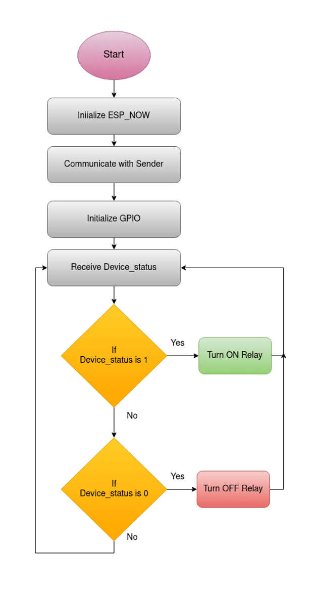
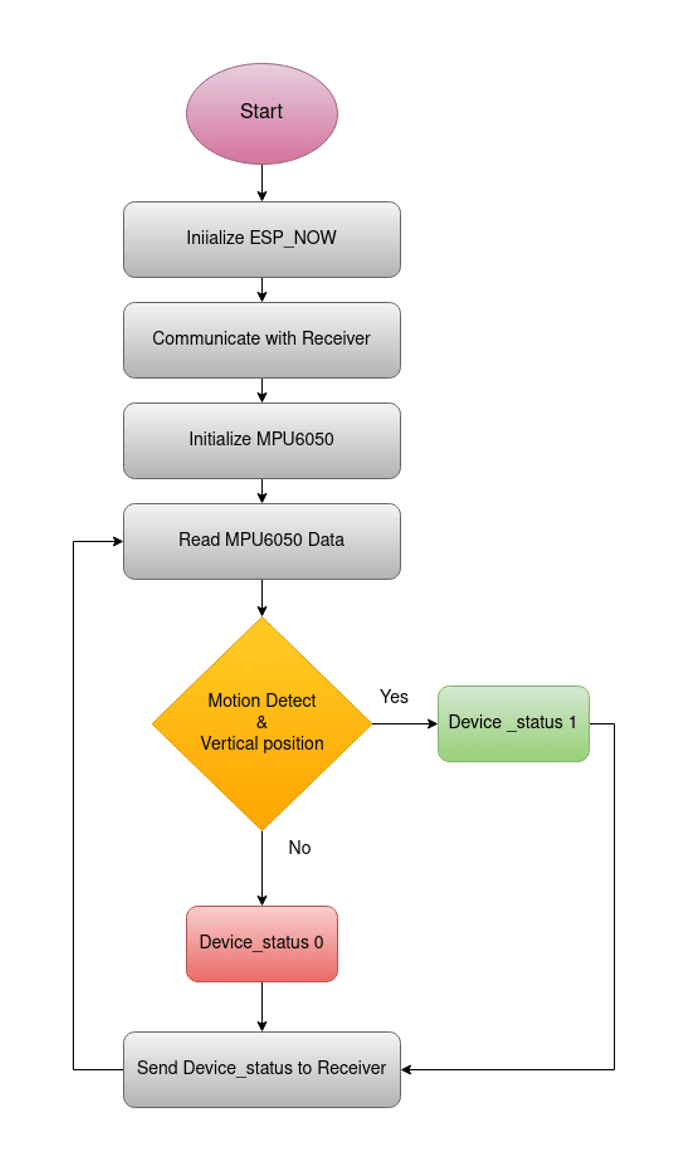
Firmware description
The firmware for this system was developed in Arduino IDE using embedded C. Adafruit MPU6050 and Adafruit sensor library files are added into Arduino IDE. Once the library file is installed, connect the ESP32 development kit to the computer using USB cable and download the code for this system. The overall flow of the firmware is shown in Fig.6. and Fig.7 .